Blog
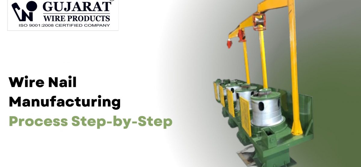
Wire Nail Manufacturing Process Step-by-Step
Most buyers who shop for nail making machines look at one number—nails per minute—without understanding the full production chain that number depends on. A nail machine rated at 400 nails per minute produces exactly that when every upstream step delivers clean, correctly-drawn wire at consistent diameter, and every downstream step—polishing, inspection, packaging—keeps pace with that output rate. Break any one link and the 400-nails-per-minute machine becomes a 180-nails-per-minute machine with a pile of rejects at the end of the shift. Wire nail manufacturing is a sequential process where each step sets the conditions for the next. Understanding the complete chain—from raw rod selection through final packaging—tells you where quality is built in, where scrap is generated, and where machine selection decisions actually matter. This guide walks through every step in order, with the technical details that operators and investors both need.
Step 1: Raw material selection
Wire nail quality starts with steel grade, not machine settings. The standard input materials are Q195 or Q235 low-carbon steel rod in 5.5–6.5mm diameter coils. Chemical composition must stay within tight limits: carbon at 0.06–0.12%, manganese at 0.30–0.50%, phosphorus and sulfur below 0.035% each.
Tensile strength in the 350–450 MPa range is the target. Higher carbon content makes the wire resist cold heading and causes nail heads to crack under punch pressure. Lower strength wire produces heads that deform under load in service. Neither failure shows up until the machine is running and nails are already in production.
Step 2: Wire drawing
The wire drawing machine reduces rod diameter from 5.5–6.5mm down to the nail wire diameter your product requires—typically 1.6–4.5mm depending on nail size. The process runs through 8–10 progressive carbide dies, reducing cross-section by 15–20% per pass.
The drawing sequence
- De-scale the rod to remove rust and surface oxide before the first die
- Apply drawing lubricant (drawing powder) to reduce friction and heat
- Pull through dies in sequence—each die slightly smaller than the last
- Anneal between passes where required for larger reductions to restore ductility
- Spool finished wire onto reels at the target diameter and coil weight (25–200 kg)
The contrarian finding: most diameter variation problems blamed on nail machine feeding issues trace back to drawing die wear—not the nail machine itself. A die worn from 2.5mm to 2.65mm wire produces feeding jams downstream that look like mechanical faults until you measure the wire.
Step 3: Wire feeding and straightening
Drawn wire feeds off the spool and passes through a set of straightening rollers before entering the nail machine. The rollers remove the coil set—the natural curve that wire develops from sitting wound on a reel—and align it straight for consistent feeding into the die block.
Straightener roller gap must be set to 0.1–0.2mm above wire diameter. Tighter than that marks the wire surface. Wider than that leaves residual curve that causes nail length variation in the forming cycle.
Step 4: Wire gripping and length feeding
The nail machine’s flywheel rotates and drives the wire forward into the die area in precise increments. Gripper dies clamp the wire at the correct position, holding it stationary while the forming and cutting cycle completes.
The feeding box advances wire by the programmed nail length each cycle. Accuracy at this step determines nail length consistency across the batch—variations here show up as out-of-spec nails that fail customer length tolerance checks.
Step 5: Nail head forming
The pin punch strikes the clamped end of the wire with controlled force, driving it into the heading die cavity to form the nail head. Head shape—flat, checkered, or countersunk—is determined entirely by the die cavity geometry and punch face design.
Heading quality depends on three factors working together: wire grade (carbon content and ductility), heading pressure (calibrated to wire diameter), and die condition (surface finish and cavity geometry). A heading defect is almost never a single-cause failure—it’s usually two of these three factors drifting simultaneously.
Step 6: Wire cutting and point forming
As the heading punch strikes one end of the wire, the cutting knives close on the other end—simultaneously cutting the nail to length and forming the point. Both operations happen in the same machine cycle, which is why cutter condition affects both nail length accuracy and point geometry at the same time.
Diamond point is the standard geometry for common wire nails. The cutting angle on the knives determines point sharpness and symmetry. Knives running past their sharpening interval produce points that are flat on one face, asymmetric, or show a micro-burr at the tip.
Step 7: Nail ejection and collection
After cutting, the gripper dies open and an expelling mechanism ejects the finished nail into a collection pan or conveyor. The machine immediately cycles to the next nail—no pause between ejection and the next wire feed.
Collection system design matters more than most producers recognize. Nails dropping onto a hard metal pan at 400 per minute develop surface dings and head marks that polishing partially corrects but doesn’t fully remove. Lined collection pans or short conveyor drops reduce surface damage before polishing.
Step 8: Polishing and finishing
Raw nails straight from the forming machine carry sharp edges, metal burrs, residual drawing lubricant, and a dull surface appearance. Polishing drums address all of these simultaneously.
The polishing process:
- Load nails into the drum with sawdust or leather shavings plus paraffin or kerosene as a polishing medium
- Rotate the drum for 20–30 minutes at controlled speed
- The abrasive action removes burrs, smooths edges, strips residual lubricant, and develops the bright surface finish buyers expect
- Discharge and separate nails from the polishing medium via a screening conveyor
Polishing time scales with nail size. Larger nails (3″–4″) need longer drum time than finishing nails (1.5″–2″) because surface area per nail is higher. Running all sizes on the same time setting produces over-polished small nails and under-polished large ones.
Step 9: Quality inspection and packaging
Before packaging, inspect against your target specifications:
- Dimensional checks: Length (±1.2mm tolerance), shank diameter (±0.05mm), head diameter and height
- Visual checks: Point geometry, head symmetry, surface finish, absence of burrs or cracks
- Mechanical checks (for special nails): Bending test, tensile pull on head, hardness for concrete nails
Pack inspected nails into bags, boxes, or bulk sacks according to order format. Store in a dry environment—even low-carbon steel nails surface-rust in humid storage within days of polishing, which creates rework or customer complaints.
FAQs
What causes nail length variation across a batch?
Three common causes: worn or misaligned feeding box mechanism, straightening rollers set too wide leaving residual coil set, or wire diameter variation above ±0.05mm that affects how the gripper dies clamp and position the wire. Check all three before adjusting the nail machine’s length setting—mechanical adjustment compensates for one cause but not the others.
Why do some nails show longitudinal marks on the shank?
Longitudinal shank marks come from the gripper die channel. When gripper die geometry wears or the channel accumulates metal debris, it scores the wire surface as it grips. The mark runs the full nail length because the gripper contacts the wire before and during heading. Clean and inspect gripper dies at every shift; regrind the channel when marks appear consistently.
How do you match polishing drum capacity to nail machine output?
Size the polishing drum to handle at least 1.5× the nail machine’s hourly output in kg terms. Running a drum at 100% fill capacity reduces polishing effectiveness because nails don’t tumble freely. A drum that’s 60–70% full produces better surface finish in the same rotation time than an overloaded drum running twice as long.
Every step sets the conditions for the next
Wire nail manufacturing doesn’t have isolated quality control points. Quality is built—or lost—continuously across the full production chain from rod selection through final packaging. An optimized nail machine can’t compensate for out-of-spec wire. Correct wire can’t fix a worn heading die. Both can’t recover what a poor polishing setup misses. The operations with the lowest scrap and most consistent output treat the entire chain as one integrated system.
Gujarat Wire Products manufactures wire drawing machines, automatic nail making machines, and polishing equipment as matched production packages—engineered and built in Rajkot to work together from wire rod to finished nail, backed by on-site commissioning, tooling guidance, and fast-turnaround spare parts from our factory team.
Ready to set up a complete wire nail production line? Visit gujaratwireproducts.com or contact our technical team for a line layout, machine specification, and wire grade recommendation matched to your target nail sizes and daily output.